Isolating a VLAN for guest Wi-Fi access on OpenWrt via LuCI
Give a guest (or any other) Wi-Fi SSID its own Layer-2-isolated VLAN on an OpenWrt device, entirely through the LuCI web UI — no SSH or manual UCI editing needed. Useful when a router/switch fabric already carries a tagged VLAN upstream (e.g. a firewall trunking a guest VLAN to the switch) and an OpenWrt AP or router needs to terminate that VLAN and hand it to a wireless network.
Prerequisites
- The VLAN must already exist upstream — i.e. it is configured on the switch (802.1Q trunking to this device’s uplink port) and/or on the router/firewall that will route and DHCP it. This guide only covers the OpenWrt/LuCI side of terminating an existing VLAN, not creating it network-wide.
- The switch port feeding this device must pass the VLAN tag through (a trunk port, not access-only).
Steps
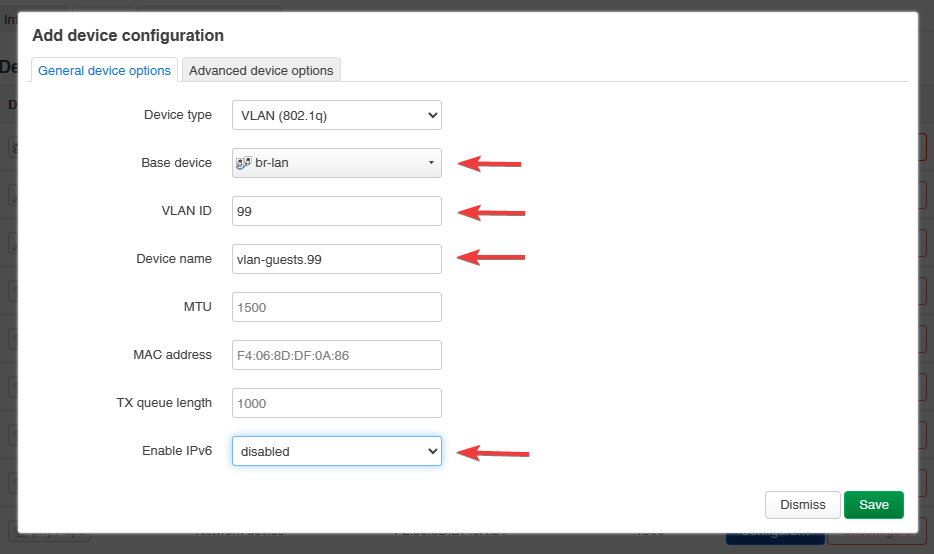
1. Create the VLAN device
Go to Network → Interfaces → Devices → Add new device → select VLAN Interface 802.1q:
- Name of the new interface: a descriptive name, e.g.
vlan-guest99 - Base device:
br-lan(the bridge the VLAN is carried on) - VLAN ID: the VLAN’s numeric ID, e.g.
99 - Optionally disable Enable IPv6-Configuration if IPv6 is not wanted on this network
- Click Save
2. Create a bridge for the VLAN
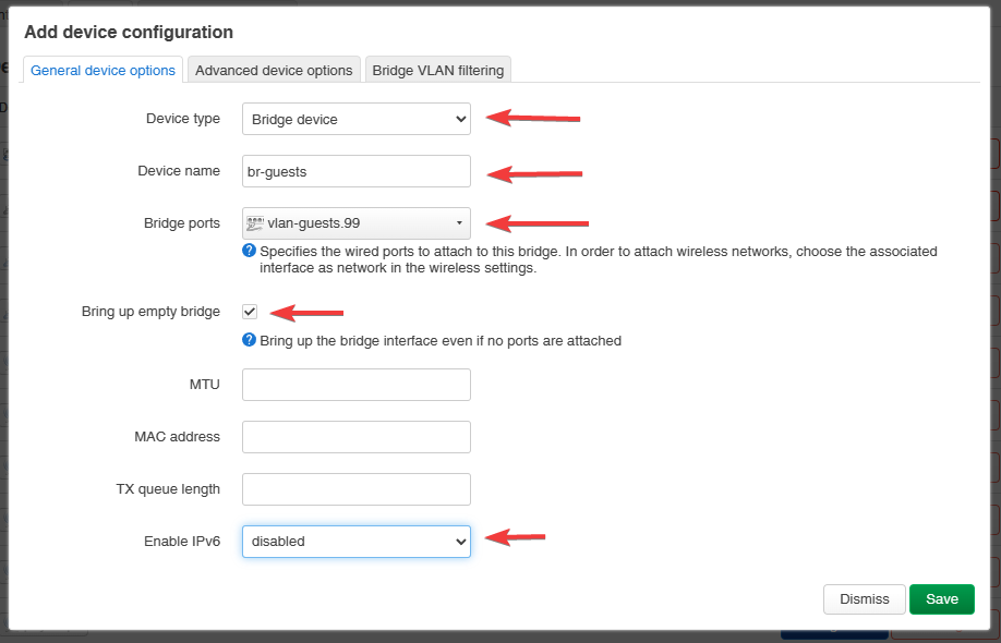
Go to Network → Interfaces → Devices → Add new device → select Bridge device:
- Name of the new interface: e.g.
br-guests - Bridge ports: the VLAN device created in step 1 (e.g.
vlan-guest99) - Optionally enable Bring up empty bridge (keeps the bridge up even with no active ports)
- Optionally disable Enable IPv6-Configuration
3. Create the logical interface
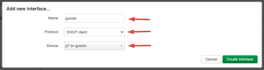
Go to Network → Interfaces → Interfaces → Add new interface:
- Name of the new interface: e.g.
guests - Protocol of the new interface:
DHCP client(assuming the upstream router/firewall serves DHCP for this VLAN; use a static protocol instead if this device itself should route/serve it) - Device: the bridge created in step 2 (e.g.
br-guests)
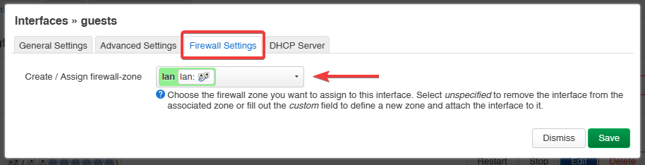
After saving, assign a firewall zone to the new interface — the simplest starting point is to
reuse the existing lan zone’s settings and adjust from there (e.g. add explicit isolation rules
if the goal is a fully isolated guest network, not just a separate broadcast domain):
4. Assign the interface to a wireless network
Go to Network → Wireless, click Edit on the SSID that should use this VLAN, and under the
Network setting select the new interface (guests) created in step 3.
Verify
- Connect a client to the target SSID and confirm it receives an address from the expected (guest) DHCP pool rather than the main LAN’s.
- Confirm the client cannot reach hosts on the main LAN if isolation is the goal — the bridge and firewall-zone setup alone gives a separate broadcast domain, not automatic client isolation; add explicit firewall rules (e.g. deny the guest zone → lan zone forwarding) if true isolation is required.
Troubleshooting
- Client gets no IP / wrong subnet: check that the switch port between this device and the upstream router actually tags the VLAN (trunk, not access port), and that the VLAN ID in step 1 matches the upstream configuration exactly.
- New SSID doesn’t come up on the interface: re-check step 4 — the wireless interface’s
networkoption must reference the exact interface name created in step 3, not the bridge or VLAN device names from steps 1–2.